Iranian Classification Society Rules

< Previous | Contents | Next >
Section 3 Welding Work and Inspection
301. Details of joints
1. Application
The details of joints for manual welding are to be in accordance with the following Paragraphs. For other welding procedures such as automatic welding and in case where the specified details of joint are deemed unpracticable, full details of joint are to be submitted for approval.
2. Butt joints
(1) In general, edge preparations of butt welds are to be as shown in Fig 2.2.4.
(2) Butt welded joints of plates having difference over 4 mm in thickness are to be properly ta- pered at the end of thicker plate.
3. Butt joints of thick materials
The groove of thick materials, such
2.2.5.
as cast steel, is in general to be prepared as shown in Fig

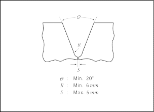
Fig 2.2.4 Edge preparation Fig 2.2.5 Butt Joint of Thick Material
4. Lap joints
(1) The breadth of overlap for lap joints which may be subjected to bending is not to be less than obtained from the following formula, but need not exceed 50 mm.
![]() = 2
= 2 ![]() + 25 (mm)
+ 25 (mm)
where:
![]() = Thickness of the thinner plate (mm)
= Thickness of the thinner plate (mm)
(2) Where plates are joggled, the breadth of overlap for joints which may be subjected to bending is not to be less than obtained from the following formula, but need not exceed 40 mm.
![]() =
= ![]() + 25 (mm)
+ 25 (mm)
where:
![]()
= Thickness of the thinner plate (mm).
![]()
302. Welding Practice
1. Welding Practice, which is the detailed statement of the general welding works for hull structure, is to contain welding process, standard of welding and its quality control, application of welding con- sumables, welding procedures specification(WPS) and welding sequence of main hull structure and be submitted to the Society.
2. The welding procedure specification(WPS) specified above is to be those satisfactorily complying with the welding procedure qualification tests specified in Sec 4.
303. Application of welding consumables
Welding consumables used for welded joints of hull structure are to be of the grades as specified in the relevant Articles of Sec 6 according to the following requirements:
(1) Application of welding consumables for welded joints of various grades of steel is to be as specified in Table 2.2.3.
(2) Welding consumables for lower toughness of steel may be used for welded joints of different toughness of steel of the same specified strength.
(3) In case of welding of steels of different specified strength, the welding consumables required for
the steel of lower specified strength may be used, provided that adequate means for preventing cracks are considered.
![]()
(4) It is recommended that controlled low hydrogen type consumables are to be used when joining higher strength structural steel to the same or lower strength level, except that other con- sumables may be used at the discretion of the Society when the carbon equivalent is below or equal to 0.41 %. When other than controlled low hydrogen type electrodes are used, appropriate procedure tests for hydrogen cracking may be conducted at the discretion of the Society. See
![]()
Guidance
304. Preparation for Welding
1. Edge preparation
(1) The edge preparations are to be in accordance with the plans, and are to be free from moisture, grease, rust and paint which may cause injurious defects in welded joints.
(2) The edges to be welded shall be smooth, uniform and free from notches, laminations, cracks and other discontinuities which would adversely affect the quality or strength of the weld.
(3) Any injurious defects on the edges are to be removed. When weld repairs are required, con-
trolled low hydrogen type welding consumables are to be used as far as practicable and grind- ing the complete weld smooth and flush with the adjacent surface.
2. Tack welding
(1) Tack welding is to be carried out by the welders qualified by the Society.
(2) Tack welding is to be removed before the main welding for joints of strength deck plating, sheer strakes, shell plating, and other important structural members or is to be carried out by the same procedure as the main welding without injurious defect in welded joints and made with the same or higher grade of welding consumables as intended to use for main welding.
![]()
![]()
(3) The minimum length and pitch of tack welds should be in accordance with the Guidance in re- lating to Rules. See Guidance
(4) Injurious defects or any deviations from groove design due to tack welding to obstruct proceed-
ings of main welding are to be completely removed.
(5) In case of tack welding higher strength steels, high strength quenched and tempered steels or joining under high restraint, preheating is to be taken as necessary prior to tack welding.
3. Fixtures
(1) Setting appliances to be used for welding fabrications are to be so arranged as to give restraint without cracks and other defects in welded joints.
(2) Tack welding for temporary fittings is not to leave any defect on base metal after the tack welds have been removed.
![]()
Table 2.2.3 Selection of welding consumables(rolled steel plates)
Kind and grade of steel to be welded Grade of applicable welding consumables (1)
A 1, 2, 3, 1Y, 2Y, 3Y, 4Y, 5Y, 2Y40, 3Y40, 4Y40, 5Y40, L1, L2, L3
Mild
steel
B, D 2, 3, 1Y, 2Y, 3Y, 4Y, 5Y, 2Y40, 3Y40, 4Y40, 5Y40, L1, L2, L3
E 3, 3Y, 4Y, 5Y, 3Y40, 4Y40, 5Y40, L1, L2, L3
(2) (3)
Rolled
AH32, AH36
1Y , 2Y, 3Y, 4Y, 5Y, 2Y40, 3Y40, 4Y40, 5Y40, L2
4Y42, 5Y42
, L3, 2Y42, 3Y42,
steels for
Higher
D H32, D H36 2Y, 3Y, 4Y, 5Y, 2Y40, 3Y40, 4Y40, 5Y40, L2(3), L3, 3Y42, 4Y42, 5Y42
hull
strength
EH32, EH36
3Y, 4Y, 5Y, 3Y40, 4Y40, 5Y40, L2 (3), L3, 4Y42, 5Y42
low
alloy steel
FH32, FH36 4Y, 5Y, 4Y40, 5Y40, L2(3), L3, 4Y42, 5Y42
AH40, D H40 2Y40, 3Y40, 4Y40, 5Y40, 3Y42, 4Y42, 5Y42, 2Y46, 3Y46, 4Y46, 5Y46
EH 40 3Y40, 4Y40, 5Y40, 3Y42, 4Y42, 5Y42, 3Y46, 4Y46, 5Y46
FH 40 4Y40, 5Y40, 4Y42, 5Y42, 4Y46, 5Y46
RL235A 4Y, 4Y40, L1, L2, L3
Rolled steels for low temperature services
RL235B, RL325A, RL325B
5Y42, L2, L3(4)
RL360 5Y42, L3
RL9N520, RL9N590 L91, L92
AH 43 2Y42, 3Y42, 4Y42, 5Y42, 2Y46, 3Y46, 4Y46, 5Y46, 2Y50, 3Y50, 4Y50,
5Y50
D H 43 EH 43 FH 43 AH 47 D H 47 EH 47 | 3Y42, 4Y42, 5Y42, 2Y46, 3Y46, 4Y46, | 4Y42, 5Y42, 5Y46, 3Y46, 4Y46, 5Y46, | 5Y42, 4Y46, 5Y50 4Y46, 5Y46, 4Y50, | 3Y46, 5Y46, 5Y46, 3Y50, 5Y50 | 4Y46, 4Y50, 2Y50, 4Y50, | 5Y46, 3Y50, 4Y50, 5Y50 5Y50 3Y50, 4Y50, 5Y50 5Y50 |
FH 47 AH 51 | 5Y46, 2Y50, | 5Y50 3Y50, | 4Y50, | 5Y50, | 2Y55, | 3Y55, 4Y55, 5Y55 |
D H 51 EH 51 FH 51 AH 56 | 3Y50, 4Y50, 5Y50, 2Y55, | 4Y50, 5Y50, 5Y55 3Y55, | 5Y50, 4Y55, 4Y55, | 3Y55, 5Y55 5Y55, | 4Y55, 2Y62, | 5Y55 3Y62, 4Y62, 5Y62 |
D H 56 EH 56 | 3Y55, 4Y55, | 4Y55, 5Y55, | 5Y55, 4Y62, | 3Y62, 5Y62 | 4Y62, | 5Y62 |
FH 56 AH 63 | 5Y55, 2Y62, | 5Y62 3Y62, | 4Y62, | 5Y62, | 2Y69, | 3Y69, 4Y69, 5Y69 |
D H 63 EH 63 FH 63 AH 70 D H 70 | 3Y62, 4Y62, 5Y62, 2Y69, 3Y69, | 4Y62, 5Y62, 5Y69 3Y69, 4Y69, | 5Y62, 4Y69, 4Y69, 5Y69 | 3Y69, 5Y69 5Y69 | 4Y69, | 5Y69 |
EH 70 FH 70 | 4Y69, 5Y69 | 5Y69 |
High strength quenched and tempered steels for welded structures
NOTES :
(1) The symbol of welding consumables listed above show the materials which are specified in Table 2.2.16, Table 2.2.25, Table 2.2.33, Table 2.2.39, and Table 2.2.67.
(2) When joining higher strength steels using Grade 1Y welding consumables, the material thicknesses should not
exceed 25 mm.
(3) Welding consumables of "L2" is applicable to steel grade of A H32, D H32, E H32 or F H32.
(4) Welding consumables of "L3" is applicable to steel grade of R L325B .
![]()
Rules for the Classification of Steel Ships 2015 117
![]()
305. Welding sequence and direction of welding
1. Welding sequence and direction of welding are to be so determined as to prevent defects in welded joints and to minimize deformations caused by welding.
2. The joints which may cause excessive contraction by welding are to be welded as far as practi- cable prior to the joints which cause smaller contraction by welding.
3. Welding is to be proceeded to free ends of the joints as far as practicable and welding with direc- tion of vertical-downward is not to be carried out, except the special approval of the Society.
![]()
![]()
See Guidance
306. Main welding
1. Welding is to be carried out so that no injurious defects may exist in the joints.
2. Welding is to be carried out under conditions of protection against the deleterious effect of mois-
ture, rain, wind and snow, and is to be preheated in cold weather if found necessary.
![]()
Guidance
![]()
See
3. The ends of important welded joints are to be fitted with run-off tabs or are to have proper ex- tensions, which are to be cut off after finished welding.
4. Butt welded joints are to be back chipped to remove the defects in root of welds before applying the closing bead, except in case of one side welding or other approved procedures.
5. In case of welding under excessive restraint or welding for thick steel plate, cast steel or forged steel, special precaution is to be taken as necessary, such as preheating of the material, use of low hydrogen electrodes, etc. so as to prevent cracks.
6. In the parts subject to excessive stress concentration, the fillet welding is to be carried around the ends of member, but in other parts, the fillet welding may not be carried out around the ends, pro- vided that the craters at the ends of welds are filled up.
7. Excessive gaps in butt joint are to be either deposited with welding on grooves, fitted with backing strips to the joints or partly replaced, and are not to be spanned with welding nor filled by slugging.
![]()
8. Where the gap between the members in fillet joints is not greater than 2 mm, the welding may be done with the given size of fillet. Where the gap is not less than 2 mm nor more than 5 mm, the welding is to be done with an increased size of fillet corresponding to the amount of gap. Where the gap exceeds 5 mm, the welding is to be done inserting a liner of suitable size or with a chill strip, or plates to be welded are to be partly renewed. See Guidance![]()
9. Preheating, intermediate temperature and post heat treatment are to be carried out in accordance
![]()
with the welding procedure approved beforehand or the special approval of the Society.
Guidance
![]()
See
307. Automatic welding
1. The grooves for automatic welding are to be finished in specially accurate dimensions.
2. Automatic welding is to be carried out within the inclination approved in the welding procedure qualification test.
3. In the cross but joints of 16 mm or over in thickness, one joint is to be welded after the auto- matic welding of the other joint has been completed on both sides.
4. Special precaution is to be taken as necessary for the automatic welding of rimmed steel to prevent cracks.
308. Welding for higher strength steel
1. Arc strikes are to be avoided as far as practicable.
![]()
118 Rules for the Classification of Steel Ships 2015
![]()
2. Short bead, min. length of repair welds and line heating temperature, etc. are to be in accordance with the Shipbuilding Quality Standard recognized by the Society.
309. Quality of welds
1. The weld is to have a regular and uniform surface and it to be reasonably free from excessive re- inforcements, injurious defects, such as undercuts, overlaps, etc.
2. Welded structures are to be reasonably free from welding deformation.
![]()
![]()
3. Non-destructive inspection is to be carried out for welded joints as the Guidance relating to the Rules specified elsewhere. See Guidance
4. The welding defects found in an appropriate non-destructive inspection including the visual in- spection or watertight test are to be removed and corrected by rewelding.
310. Repairs
1. The removal of weld defects shall be done by gouging, grinding, chipping, etc. with such a manner that the remaining weld metal or base metal is not damaged, however oxygen gouging is not to be used in high strength quenched and tempered steels.
2. The removed weld defects parts are to be so machined as not to affect repair welding and repair welding shall be carried out with low hydrogen type welding consumables and an electrode pref- erably smaller than that used for making the original weld.
3. Members distorted by welding may be straightened by mechanical means or localized heat treat- ment, however in case of localized heat treatment, the temperature of heated areas is to be so lim- ited as not to affect the mechanical properties of base metal.
311. Welding works for YP47 Steel Plates
![]()
![]()
The welding works for YP47 Steel Plates are to be in accordance with the Guidance in relating to Rules. See Guidance
![]()
Rules for the Classification of Steel Ships 2015 119
![]()
![]()
![]()